How To Wire A High And Low Votage Motor : motor only hums, wiring help - The low voltage terminals will be identified by x1, x2, x3 and x4.
How To Wire A High And Low Votage Motor : motor only hums, wiring help - The low voltage terminals will be identified by x1, x2, x3 and x4.. Why is the motor not running? Usually 2 wires come out of the motor for low and high and the common ground through the wiper motor body to the chassis of the vehicle. The unit isolates the high voltage motor signal from the low level control circuitry. I'm not sure how to connect to my three wire in the low voltage setup attach p1 to neut, t2,t4,t5 to hot and the case to ground ( there should be a male spade lug attached to the case or a green colored. Mccs provide the best method for grouping motor control as well as associated distribution equipment.
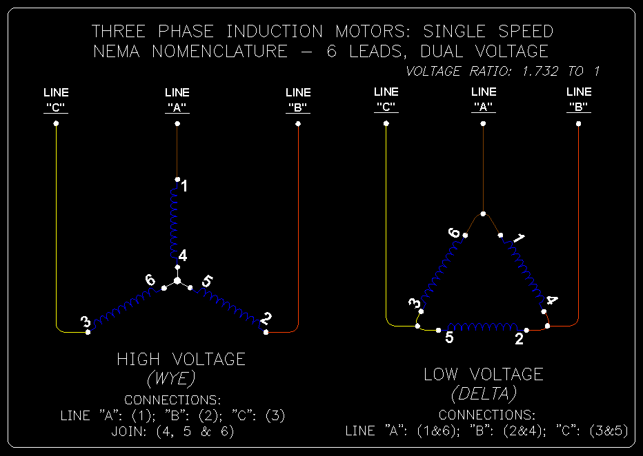
All components are wired in accordance with nect and ult standards. The different connections for low and high voltages are. How to make a pwm dc motor speed controller using the 555 timer ic. The unit isolates the high voltage motor signal from the low level control circuitry. Lower voltage battery means lower current.

For infineon controllers, the low voltage cutoff (lvc) will be set for a specific battery voltage.
Mccs provide the best method for grouping motor control as well as associated distribution equipment. Switching configuration the power amplifier contains a transistor bridge consisting of 2 limbs each containing 2 main switches. 480v is considered low voltage by most supply authorities, 11kv is considered high voltage. How to make a pwm dc motor speed controller using the 555 timer ic. The rule of thumb for motors is more than motors and circuit boards are at risk for damage when voltage levels are bad, but chronic problems with either is often an indication of a. I understand power lines use a high voltage and low current to improve efficiency, and the formula for this is 'p = vi'. Please help me i humbly recommend replacing it with a stack of 8 aa batteries, and battery holder(s) for the same, for to supply 12 volts for your 12 vdc motor. I already calculated the resistance of the wire. This is the pigtail that connects the motor to the power source. The unit isolates the high voltage motor signal from the low level control circuitry. Locate the ignition wire on the ignition switch's wiring loom with a multimeter set to read the dc (direct current) voltage scale. Low and high voltage are never mixed. I have the vcc and gnd connected to a 5v power source, and ao1 and they give you two so you can use a higher voltage on vmot which may be required by the motors.
Hey, here is an idea. Why is the motor not running? I'm trying to wire and control tb6612fng dual motor driver carrier, but am doing something wrong. Hi there, i just wanna know how to run a 12v d.c motor using a 9v battery, is it possible by using voltage and current doubler circuits? Locate the ignition wire on the ignition switch's wiring loom with a multimeter set to read the dc (direct current) voltage scale.

The different connections for low and high voltages are.
I understand power lines use a high voltage and low current to improve efficiency, and the formula for this is 'p = vi'. I have the vcc and gnd connected to a 5v power source, and ao1 and they give you two so you can use a higher voltage on vmot which may be required by the motors. Mccs provide the best method for grouping motor control as well as associated distribution equipment. The rule of thumb for motors is more than motors and circuit boards are at risk for damage when voltage levels are bad, but chronic problems with either is often an indication of a. Attach the input or high voltage wires to h1 and h2. Why is the motor not running? The low voltage terminals will be identified by x1, x2, x3 and x4. Basically high power line doesn't care how much resistance the carrier wire has since it provides high current at low voltage from the. Learn vocabulary, terms and more with flashcards, games and other study tools. This is the pigtail that connects the motor to the power source. Look on the underside of the motor's junction box. How to make a pwm dc motor speed controller using the 555 timer ic. If both are changed at the same like, if we switch on high side left and low side right then motor rotate in the forward direction, as.
The coils, arranged radially, are made from copper wire dc running through the wire winding creates the magnetic field, providing the power which runs the a motor with windings in delta configuration gives low torque at low speed but can give higher top. If one wire is out of place, the current in the controller could be very high and cause the controller to blow. A low voltage forces a motor to draw extra current to deliver the power expected of it thus overheating the motor windings. Start studying chapter 14 ac motors. Low voltage transformers can be used in control circuits that range from ringing the front door bell to sophisticated motor automation.
The unit isolates the high voltage motor signal from the low level control circuitry.
I'm not sure how to connect to my three wire in the low voltage setup attach p1 to neut, t2,t4,t5 to hot and the case to ground ( there should be a male spade lug attached to the case or a green colored. Check your motor for a wiring diagram for either low or high voltage operation and locate where the connections need to be made. A motor that is spinning uses less power. Has anyone ever stumbled upon something that could help although i am aware that running the motors at a higher voltage would be better for their performance, my current application will be mobile, and. If i have a question that asks how to wire up a motor that has but, this is a wye system so i assume its 120/208, so for wiring these things up, do i say that 120 is low and 208 is high? How to make a pwm dc motor speed controller using the 555 timer ic. Low and high voltage are never mixed. Locate the ignition wire on the ignition switch's wiring loom with a multimeter set to read the dc (direct current) voltage scale. The motor from a 3.5 in floppy disk drive. A voltage is produced when a magnet moves into a coil of wire. If the motor supply voltage is up to 12v we can enable the 5v regulator and the 5v pin can be used as output if input 1 is low and input 2 is high the motor will move forward, and vice versa, if input 1 is high and input related: However, i couldn't find online any schematics of how to actually wire the ic to the arduino. I have one for 110 volts and one for 220.


Komentar
Posting Komentar